Marine Engineering
Marine engineering services include both traditional and computational FE analysis methods. In addition, 3D scaled models can be created from CAD models in order to simulate and verify interaction between modelled components.
Marine Structural engineering services include:
- Expert Witness services
- Support for salvage operations
- Finite Element Analysis and Computational Fluid Dynamics.
- Traditional structural analysis
- Development and Testing of Bespoke Structural Components
- Computational Simulations and drawings
- 3D Rapid Prototype Models and Simulations
- Design and development of 3D scaled functional models
The types of FEA and CFD analysis methods available are as follows:
- Structural FE Analysis - 3D Design, Explicit and Implicit, Linear and Non-Linear, of Steel, and Composite structures including:
- Static analysis
- Buckling
- Nonlinear
- Linear Dynamic
- Fatigue analysis
- Pressure vessel Design
- CFD - Typical modelling services include:
- Determination of drag coefficients around hulls
- Heat Transfer
- Ventilation
- Mixed Flow Simulation
- Fluid-Surface Interface (FSI)
- Development of Innovative Structural Solutions
Case Studies for some recent applications of Marine Engineering
Please see some recent applications relating to our work in Marine Engineering - Click on thumbnails to see a larger image and slideshow.
Expert Witness work
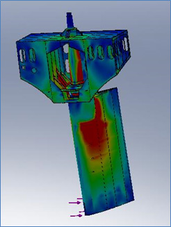
The Standard Vigor
The ‘Standard Vigor’, a bulk-carrier, had sustained severe rudder-stock damage due to alleged grounding impact with a river-bed.
In order to determine the feasibility of such an event, an assembly comprising the rudder, rudder stock and a section of the stern were modelled and analysed over a range of rudder deflections by means of static linear and non-linear FEA.
Comparison of the FEA generated stress contours with the actual damage showed that the alleged incident could not have occurred due to a grounding incident since no plastic deformation was found within the rudder, in contrast to the FEA simulation. In addition, the propeller tip extended below the rudder and was found to have been undamaged. This indicated that the river bed was made of soft material that could not have given rise to the type of reactive loads necessary to bend the rudder stock.
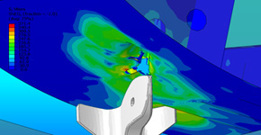
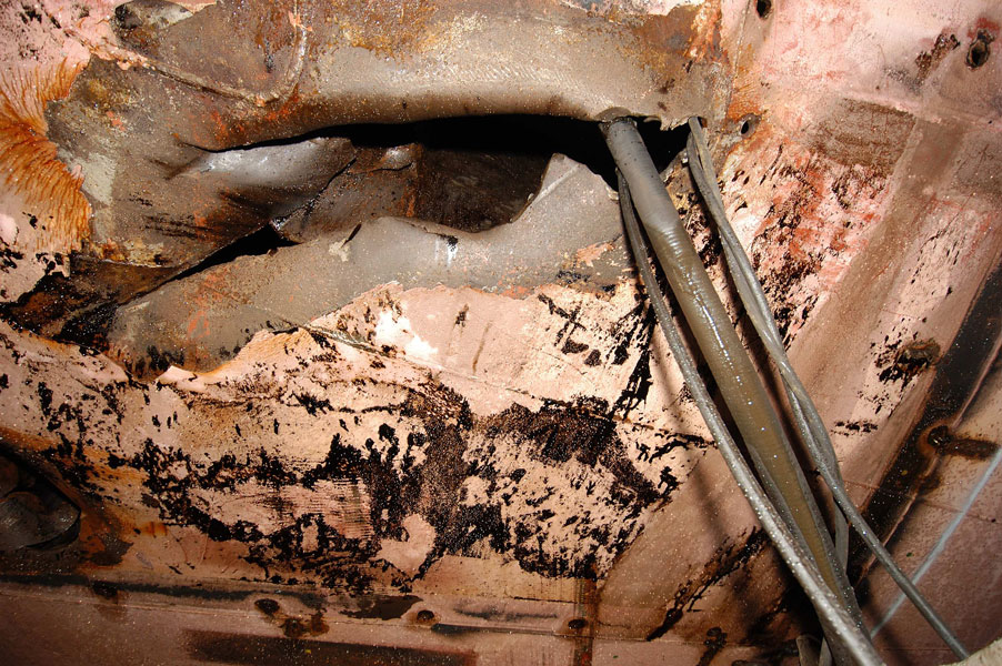
The Athos-1
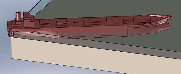
An oil tanker, the ‘Athos 1’, had its hull punctured, during docking manoeuvres, by a discarded anchor on the bed of the Delaware River in Philadelphia US, that resulted in severe environmental pollution due to a spill of cargo of crude oil.
In order to determine the height of the vessel from the riverbed at the time of the accident, it was necessary to establish the position of the anchor during impact. The only means of doing so was by comparing the damage that an anchor could have caused in two positions: with its flukes in the upright position and with its flukes lying on the river bed. In-turn this would enable to assess the height of the vessel bottom from the riverbed.
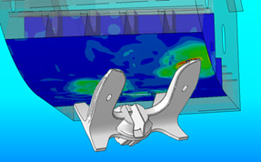
A non-Linear Explicit FE Analysis of the anchor Impact with the hull of the Athos-1 established that due to the damage pattern, the damage could have only occurred with the flukes in the upright position. The simulated damage pattern that a Palm impact would have caused was entirely different from the actual observed damage and could not have allowed disentanglement from the hull without causing further damage.
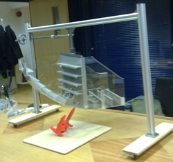
For further visualisation of the relative positions and orientation of the anchor and hull, scaled physical models were created. The hull was mounted on a travelling gantry frame that enabled to examine the emerging position of the anchor at the time of impact.
Both the FE simulations and the physical models confirmed that the accident could have only happened with flukes in the upright position. Furthermore, the accident occurred because the vessel was travelling in a direction that was parallel to a line extending between the flukes and this is why the anchor could not be deflected and was forced into the hull.
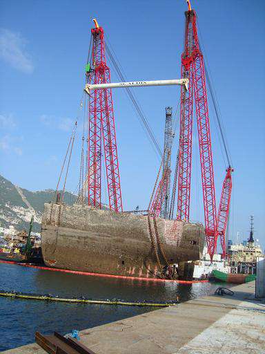
Salvage Operations
The ‘New-Flame’ was lost in shallow water in the Eastern Mediterranean. During salvage operations it was necessary to establish the strength of a deck section due to lift loads.
To that end, the deck section of the ‘New-Flame’ was modelled and analysed by means of static linear FE.
Results showed that a lifting beam was required in order to prevent excessive deformation of the deck. The lift went ahead successfully.


Tank-Top Structural strength
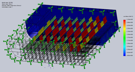
The tank top of a Bulkhead carrier, the ‘SAGA’ was to carry a load of steel.
In order to determine the structural capacity of the deck was analysed by means of linear static FE, for determination of its capacity to sustain the loads of rolls of steel plate of various sizes and weights.
The analysis showed that loads had to be placed over main girders and that the loads must be spread by means of timber spreader-plates in order to avoid local buckling.